1.What is 3D Printing or Additive Manufacturing?
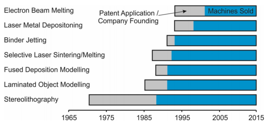
The objects produced by 3D printing processes can have almost any shape or geometry. They are typically produced using digital model data from a 3D model or other electronic data source such as an STL (STereoLithography) file, one of the most common file types that 3D printers can read. The term 3D printing originally referred to a process in which a binder material was deposited layer by layer onto a powder bed using inkjet print heads. More recently, the term 3D printing has come into common usage to encompass a broader range of additive manufacturing processes. Among professionals, the term additive manufacturing remains more popular due to its broader meaning and longer existence. Other terms are also used, such as desktop manufacturing, rapid manufacturing, direct digital manufacturing and rapid prototyping. The invention of additive manufacturing can be traced back to the 1980s to Japanese, French and American researchers. The very first patent for 3D printing was filed in 1984 by Chuck Hull of 3D Systems Corporation. Hull defined the 3D printing process as a system for building three-dimensional objects by creating a cross-sectional pattern of the object to be formed. His invention consists of a stereolithography manufacturing system in which layers are added by curing photopolymers with ultraviolet light lasers. Stereolithography remains a very popular 3D printing manufacturing technique, also known as SLA.
However, the technology used by most 3D printers in the 2010s, especially by hobbyists and consumer-oriented products, is fused filament fabrication (FFF). It is also known as material extrusion or fused deposition modelling (FDM), the proprietary name of Stratasys. FDM was patented by S. Scott Crump in 1989, shortly before he founded Stratasys with his wife, Lisa Crump. Metal 3D printing did not become available until the 1990s with the invention of laser melting and sintering. Selective laser sintering (SLS) and selective laser melting (SLM) can also be referred to as direct metal laser sintering (DMLS) and direct metal laser melting (DMLM) when metal is the processed material.
2.How to choose the right 3D Printing Technology?
3D printing or additive manufacturing is an overall term that includes several processes. Most of them were developed in the 1980s-90s. Each 3D printing process has its advantages and limitations, and each suits better to a certain application than others. In this unit, we’ll give you some easy-to-use tools to help you to choose the right 3D printing process for your needs.
2.1 Overview of relevant basic 3D printing technologies
2.2.1 (FDM) 3D Printer | FDM for Functional Prototypes.
The FDM technology has attractive strength values in the strand direction and thus enables the printing of first functional prototypes.
General Process
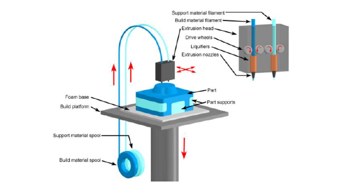
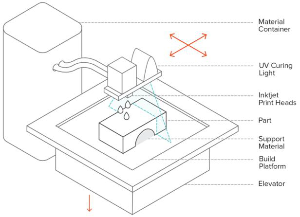
Fused Deposition Modelling (FDM) sometimes referred to as Fused Filament Fabrication or FFF is the most commonly used 3D printing technology. FDM produces parts with strands of solid thermoplastic material that is in the form of a filament. The filament is pushed through a heated nozzle where it is melted. The printer continuously moves the nozzle around, depositing the melted material in precise locations that follow a predetermined path. As the material cools it solidifies and builds the part layer by layer. This unit will give you a good overview of FDM and what the technology’s capabilities and problems are.
Material Feed System
Bulk material is either loaded directly into an extrusion chamber or continuously fed to the print head from a hopper or spool. Pellets are pushed through by a screw conveyor and filaments by rollers/wheels. Filament from a roll is most commonly used. As shown in the figure above, some printers use multiple nozzles. For example, multiple types of material can be used in one component. In the illustration, the construction material is used once, and a special wash-out material is used for the support structures. This process was mainly driven and developed by Stratasys.
Deposition Characteristics
The shape and flow rate of the deposited material depends on the dimensions of the nozzle. There is a trade-off between the speed at which the system deposits the material and the quality of the part. The flow rate of the material and the movement of the extrusion head must be synchronized to ensure consistent deposition and accuracy. The direction of the extrusion head movement is subject to rapid accelerations and decelerations. Minimizing the weight of the extrusion head is important to reduce inertia and facilitate stopping, starting and changing directions. In post-processing, depending on the printer, it is possible to influence the flow speed and the travel speed of the print. Usually the pre-set profiles are sufficient and only for special materials or process optimization parameters should be adjusted. Experience shows that FDM processes in the low-cost range require some trial and error to achieve consistently good results.
Support Structures
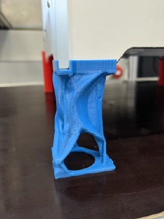
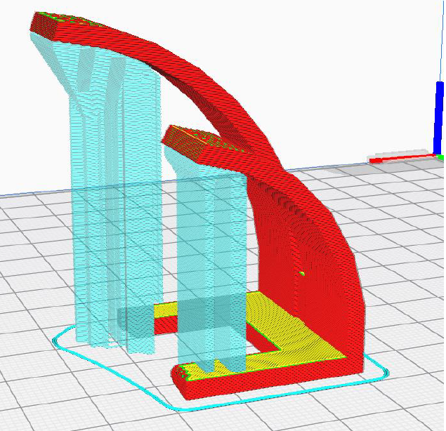
Extrusion-based systems require support structures for overhanging and undercut parts during production. The support structures can be made from the same material as the rest of the part or from a different material. Colour variation helps to see the difference directly. Support material patterns can be automatically generated by the AM software. By design, support structures can be avoided. A rule of thumb is that overhangs up to 45° can be printed without support structures. Up to 65°, many printers also still achieve good results. To test which overhangs can be printed, test prints like the following are recommended. Our benchmark print also covers this.
If you are designing your part yourself, design cleverly and try to change your overhangs so that they are a maximum of 65°. Less support material will result in shorter print times and less need for rework. In the following you can see how the actual component (red & yellow) is held by blue support structures from 65°.
Without support material, unsupported features can deform due to gravity. Powder bed systems that use polymer powder do not require support material because the excess powder holds the part. Extrusion-based technologies print the support structure in the same manner as the base material. Inexpensive printers usually print their support structures from the same material as the actual part. This has the disadvantage that it has to be removed manually close to the print and leads to less good surfaces. This is often used to save costs. In this section, two common substrate materials are presented, which are used to be able to be washed out, for example:
High Impact Polystyrene (HIPS):
High impact polystyrene is a polymer with strength and durability comparable to ABS. It is often used in conjunction with ABS as a substrate. HIPS filaments are inexpensive and can be dissolved in various solvents during post-processing. The main advantages are dissolvability in limonene and low toxicity, while the disadvantage is that the solvent can be costly.
Polyvinyl alcohol (PVA):
Polyvinyl alcohol or PVA is a synthetic polymer that is soluble in water. PVA is suitable as a carrier for PLA parts, but not for ABS, because PVA and ABS do not adhere well and have different extrusion temperatures.
Printing Patterns and Anisotropy
The outline of a cross-cross section is printed first at a slow rate to optimise the part’s dimensional accuracy. Then, the system normally fills in the inner areas using a cross-hatch pattern. The nozzles have circular outputs, therefore it is challenging to plot corners. Different filling patterns and layering strategies can result in varying material properties in different directions (anisotropy).
FDM components are anisotropic. This means along the layers their load capacity is at 100%. Orthogonal to the layers, the tensile strength is reduced to approx. 30%. This is to be considered if you want to load components in a certain direction. Orient them so that the main load is along the layers.
Advantages and Disadvantages
Each manufacturing process has its individual advantages and disadvantages. The following are the main advantages and disadvantages of FDM.
Pros:
FDM parts are stable and suitable for functional parts.
● Machines are suitable for office environments.
● FDM parts are stable in the long term.
● Resistant to UV light, chemicals.
● Wide range of post-processing possibilities.
● Wide range of materials.
● Soluble support materials.
Cons:
● Fluted surface.
● Anisotropy of mechanical properties.
● Slow process.
● High part cost compared to other plastic AM processes.
● High demand for support structures.
Machine Costs
Home users and hobby
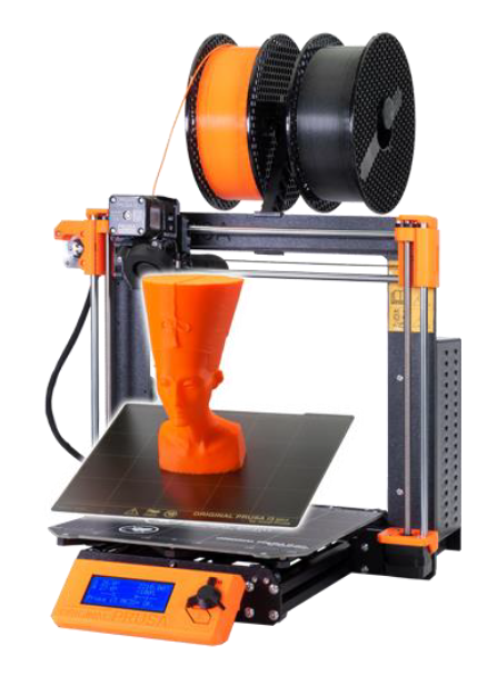
FDM is one of the most affordable ways to get started in additive manufacturing, even for home use. Cheap usable devices are available for 250€ (as of 2021) and very good hobby devices, which can also be found in small companies and startups, start at 1000€. Simple printing material like PLA is already available from 20€/kg. Better materials can cost from 50-200 €/kg.
Entry-level devices are available from Anycubic for example. Especially recommended are the devices from Prusa. Typically, the build space is in a range from 200 x 200 x 200mm to 500 x 500x 500mm with a minimum layer thickness of 0.02mm.
Prototype and Development
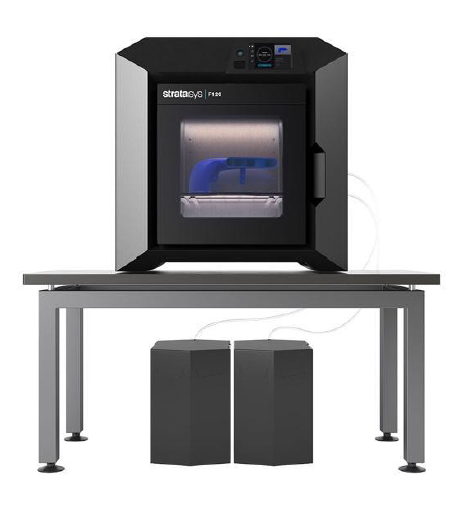
In prototyping and development, semi-professional FDM printers are a good way to achieve results quickly and comparatively cheaply. These devices require less maintenance than in the hobby sector and have been working very reliably for years. Typically, the devices cost between 5000€ and 25000€ (as of 2021). Manufacturers such as Stratasys, Ultimaker and Makerbot are more common here.
Manufacturing
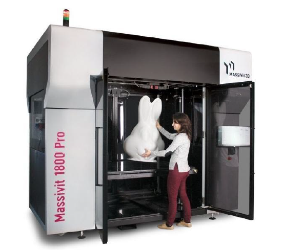
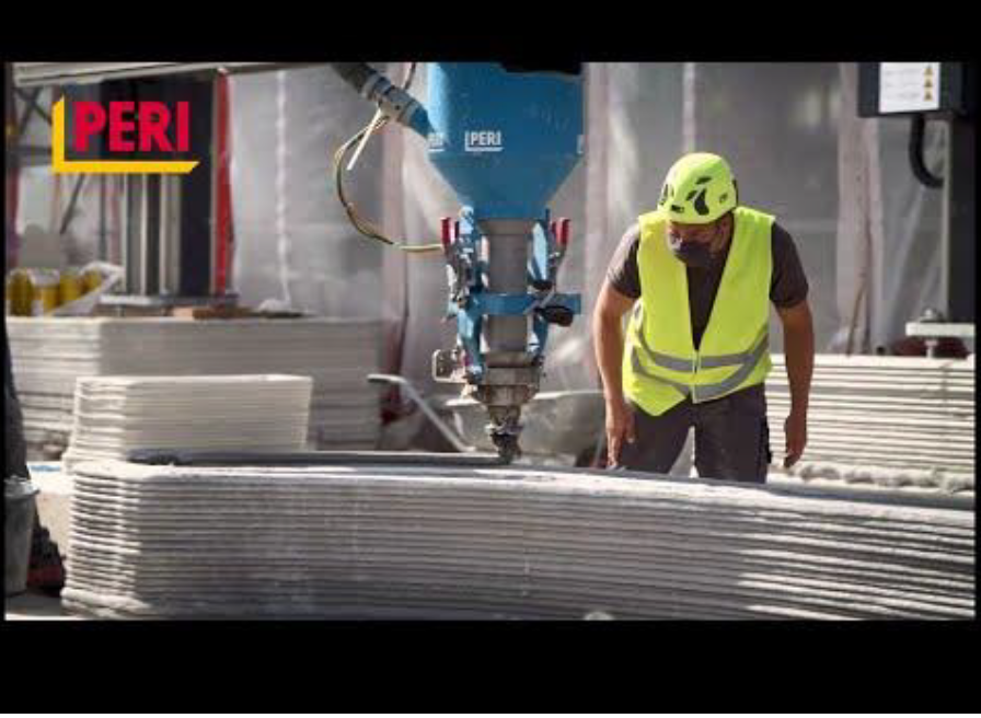
In the large format and manufacturing there are FDM printers in the price range from 50000€ to 300000€. The technology is only suitable to a limited extent to produce larger quantities, but very large models are feasible. Typically the Build space is in a range from 500 x 500 x 500mm to 1500 x 1500x 500mm with a minimum layer thickness of 0.04mm. Thus, FDM is also used in the field of architecture. The company Massivit offers large-format printers. The company Peri uses the FDM process for prints made of concrete.
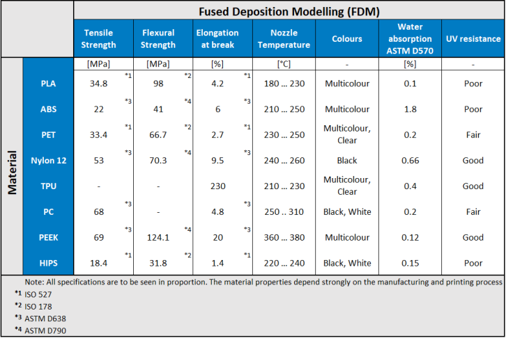
Materials and Properties
The following table gives an overview of the materials typically used in FDM. PLA is the most widely used material in the amateur and hobby sector. If there are high demands on the component, PEEK is used. However, this material can only be processed on professional equipment.
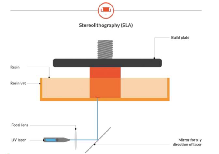
2.2.2 (SLA) 3D Printer | Stereolithography for functional prototypes and series parts.
The SLA stereolithography systems for functional prototypes and series parts are the entry into the world of PRODUCTION 3D printers and offer superior part quality and accuracy in generative layering. The wide range of materials from robust, flexible, black and transparent materials to dental, jewellery and high temperature materials qualify these 3D printers for a wide range of applications.
General Process
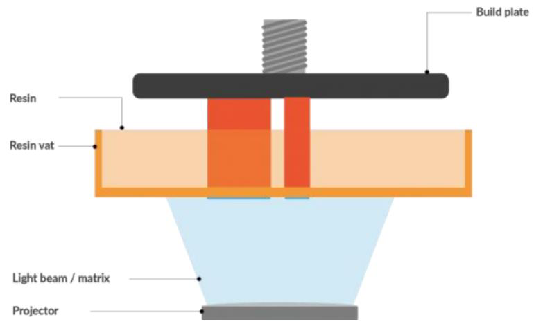
Stereolithography (SL or SLA) is the oldest 3D printing technology, developed and patented by Charles W. Hull in 1986. In SLA manufacturing, a UV laser scanner system traces 2D contours of cross-sections of a 3D model on a tub of photopolymer resin. The scanner system consists of mirrors and a lens that direct and focus light in the XY plane. The build platform is submerged in the resin and moves the part down (in the Z direction) once a layer is scanned. The part can be made from the bottom of the vat up (consumer printer) or from the top of the vat down (professional printer). When the printer projects the light beam onto the bottom of the vat, the part is held at a layer distance from the bottom surface. The resin is forced under the part due to gravity and then cured with the UV laser before being peeled off so another layer can be applied. Alternatively, there are setups in which the resin is spread with a sweep blade. The part is at greater risk of being damaged during peeling, but is less susceptible to defects caused by uneven layer surfaces because new layers are always in contact with the bottom of the shell.
The liquid resin is solidified by a process called photopolymerization: during solidification, the monomeric carbon chains in the resin are activated by the light from the UV laser. The chains solidify, forming strong, unbreakable bonds between them. The photopolymerization process is irreversible and there is no way to convert the SLA parts back to their liquid form: when heated, they burn instead of melting. Unlike the thermoplastics that FDM uses, the materials produced with SLA are made of thermoset polymers. Tolerances on an SLA part are typically less than 0.05 mm, and it offers the smoothest surface finish of any additive manufacturing process. SLA is all about precision and accuracy, so it is often used where shape, fit and assembly are crucial. Given the level of quality that can be achieved with SLA, it is particularly useful for creating high-precision casting patterns (e.g., for injection molding, casting, and vacuum casting), as well as for functional prototypes, presentation models, and for performing mold and fit testing. It is the preferred choice for designer models and engineering reviews. SLA technology is extremely versatile and can be used in all areas where precision is required above all else.
With the SLA printing process, it is important to know how to post-cure your resin 3D prints. Post-curing allows parts to reach the highest possible strength and become more stable. This step is especially important for functional resins. For example, post-curing is required for successful burnout in castable prints, and flexible resin doubles its strength with post-curing. If you are using a stereolithography (SLA) 3D printer it is important to know how to post-cure your resin 3D prints.
Technology
In contrast to FDM, SLA printers are generally more professional. In the FDM field, there are extremely cheap and simple entry-level models, which require a variety of configurations for the printing results to be good. In SLA, less customisation is required. The manufacturer’s software is highly optimised for the processes and materials.
However, there are some key elements that have a significant impact on print quality and speed. However, these can only be influenced by very experienced users. The accuracy of the components depends largely on the cure depth and width of the laser.
Cure Depth and Width
In stereolithography, the width of a cured resin line depends on the shape of the scanned line, with larger scan beams producing deeper depths of cure. The amount of energy transmitted by the laser beam also affects the depth of cure. If the energy is too low or the scan speed is too high, not enough energy is transferred to cure the polymer. A simple way to adjust the exposure energy is to adjust the scan speed. The minimum amount of energy required is called the critical exposure energy, which is a material property of the resin.
Photospeed
The photospeed is the speed at which the polymer is cured at a certain depth relative to the surface. It depends on the material properties, verified experimentally, including the critical exposure and the depth to which the laser can penetrate the resin.
Time Scales
The characteristic exposure time is the time required to scan a spot on the resin to cure it. It is usually between 50 and 2000 microseconds and depends on the scanning speed. After exposure, the resin continues to react and shrink. The chemical reactions can take anywhere from a fraction of a second to ten seconds. The shrinkage occurs because of the newly formed polymer occupying less space than the photopolymer resin.
Weave
In stereolithography, the beam solidifies a layer before adhering it to the previous one. This separation is made to prevent adjacent layers from affecting each other as they shrink at different times. The laser scans lines in the X direction first and then in the Y direction, to give the first lines just enough energy to adhere to the previous layer.
Weave Patterns
Scanning new lines directly on top of each other can improve part properties. On the other hand it introduces distortion at the corners and can create significant internal stresses. To solve these problems, a “star weave” pattern was introduced.
Supports
SLA always requires support structures. These consist of three components: rafts, scaffolds and touchpoints. The scaffold forms a base that adheres to the build platform. The scaffold protrudes from the plate to secure your part during printing. Touchpoints are contact areas where the framework meets the model. If your model is not adequately supported, it can cause the following:
● Partially cured resin floating in the tank that needs to be filtered out.
● Misaligned layers.
● Detachment of the model from the framework and supports.
● Thin walls or features may warp.
● The model may fall off the build platform.
● The part may bend severely.
● The model may settle like a pancake on the bottom of the glass tray.
Advantages and Disadvantages
Each manufacturing process has its individual advantages and disadvantages. The following are the main advantages and disadvantages of SLA.
Pros
● Rapid implementation of very accurate prototypes in early stages of product development
● Production times comparable to FDM with higher precision
● Single-step production process produces smooth surfaces with almost no post-processing (supports must be removed)
● Low material consumption: uncured resin can be reused
● Production of both flexible and rigid 3D objects
● Wide range of materials
● Cost efficient production
● Multi-part assemblies are possible
Cons
● Supporting structures can restrict design freedom
● Depending on the material, components can be brittle
● Components are only UV-resistant to a limited extent
● Components are not as highly loadable as other processes
● Cleaning effort for material changes is often high
Machine Costs
Home users and hobby
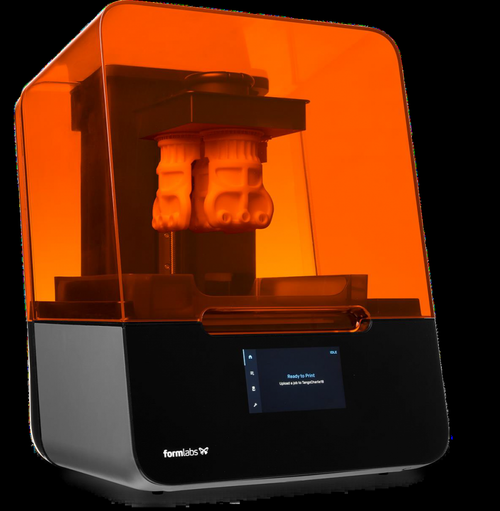
Entry-level devices are available from Anicubic for example. Especially recommended are the devices from Formlabs. Typically the Build space is in a range from 140 x 140 x 200 mm to 300 x 300x 500 mm with an minimum layer thickness of 0.01 mm. Prices for usable beginner products start at 500 € without accessories. It is recommended to purchase a wash station and a curing unit. In the hobby area, this can be replaced by a simple basin with isopropanol and a UV lamp. For an advanced entry-level system about 3,000 € should be scheduled.
Prototype and development
In prototyping and development, (semi)professional SLA printers are a good way to achieve results quickly and comparatively cheaply. These devices require less maintenance than in the hobby sector and have been working very reliably for years. Typically, devices cost between 10,000 € and 25,000 € (as of 2021).Typically the building space is in a range from 275 x 150 x 400mm to 335 x 300x 500mm with an minimum layer thickness of 0.01mm.
Manufacturing
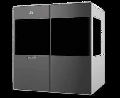
In the field of production, there are mainly devices that are designed to produce high quantities in enormously good quality. These are often equipped with several lasers and can thus reduce unit costs. Prices range from 100,000 € to 400,000 €. Typical companies are 3D Systems, DWS and Nexa3D.
Materials and their Properties
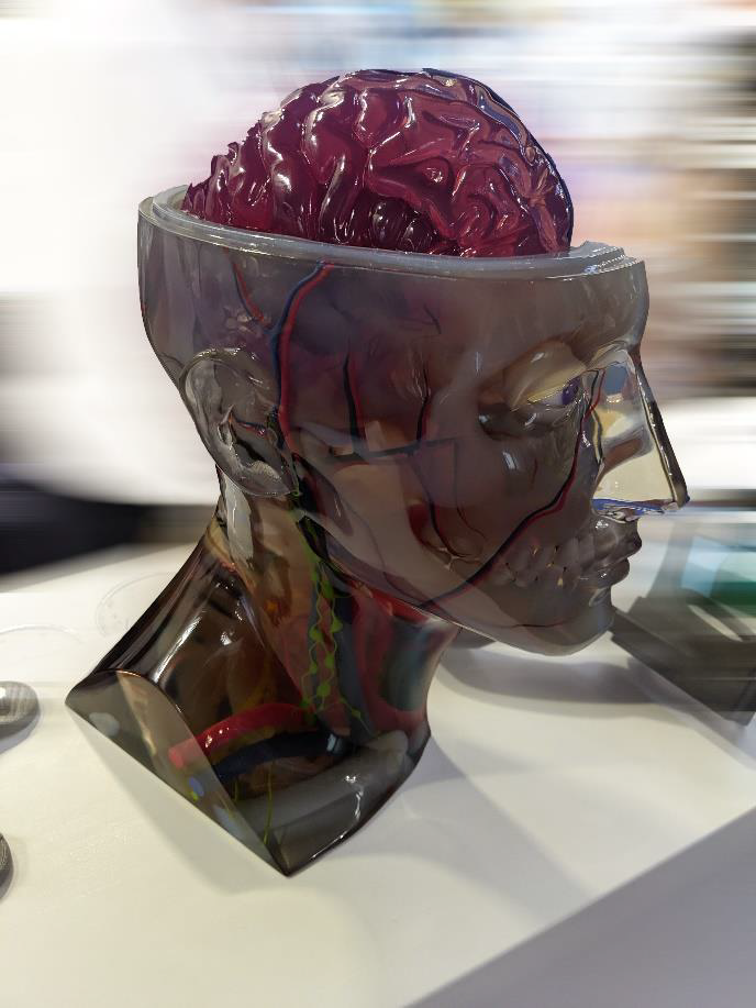
Stereolithography (SLA) is particularly well suited for parts that require high resolution and must meet tight tolerances. Thanks to the variety of resins available for SLA 3D printing, this process has found many applications in various industries. For example, in more simple applications, special technical applications or within medical technology. SLA materials have a wide range of mechanical properties and offer multiple applications for parts that require ABS or polypropylene-like properties, such as snap-fit joints, styling components for the automotive industry and master models. There are SLA materials for higher temperature applications and clear materials with polycarbonate-like properties. Casting resins, for example, are used for mold making: no ash is left when the hot cast is burned. Biocompatible materials are available for a variety of medical applications such as surgical tools, dental devices and hearing aids.
The type of resin to be used always depends on the specific printer and thus cannot be answered in general terms. The manufacturers specify which resins are recommended.
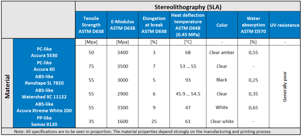
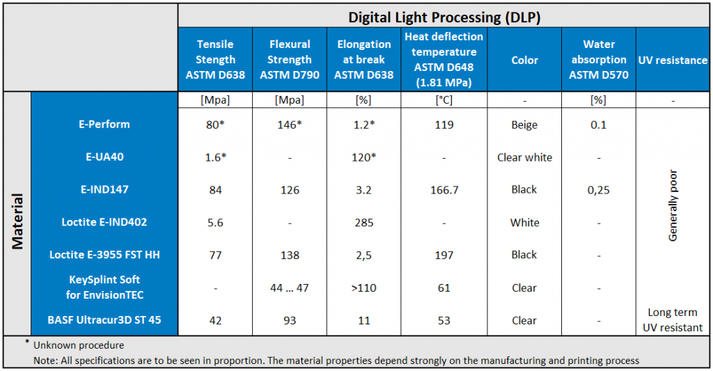
Some general material properties of commonly used materials can be found in the following table:
Special features and advantages
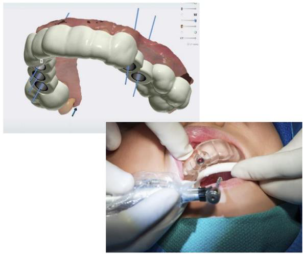
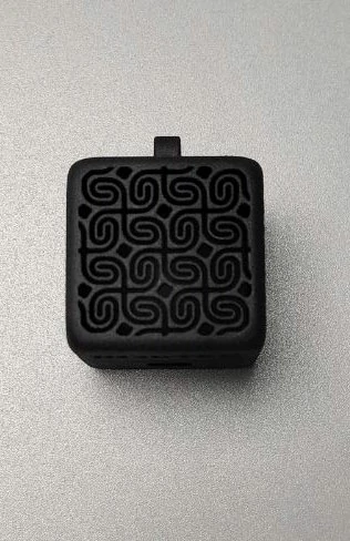
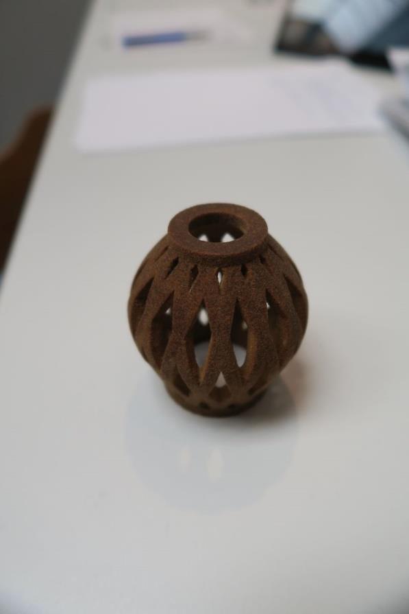
The simple implementation of the process made it possible to complete the toothbrush within a few process steps. The process was chosen because of the possibility of producing complex components or detailed objects. Since the toothbrush contains a particularly large number of narrow cuts, the possibility of creating complex components was an important criteria.
2.2.3 (DLP) 3D printing systems | Digital Light Processing
General Process
Similar to their SLA counterparts, desktop DLP 3D printers are built around a resin tank with a transparent bottom and a build platform that dips into the resin tank. The part is created layer by layer. In this unit, we will mainly show the differences to SLA. Design guidelines, error sources and material properties are similar. Those will not be discussed here.
Mask projection (MP) technologies were developed in the 1990s to project an entire cross-section of a model onto a resin surface. This method was preferred rather than using slower point-based techniques such as lasers or one-dimensional arrays. Early MP machines used LCD systems as projection devices. Modern commercial machines use digital light processing (DLP) chips to selectively direct UV light onto a resin surface to cure layers. DLP systems use digital micromirrors to turn pixels on or off in a projection. A semiconductor chip contains a large matrix of tiny digital mirrors that can be rotated ±12 degrees. At 12 degrees a mirror reflects the beam of light towards the resin. At -12 degrees the mirror blocks the light beam that illuminates a pixel at the base of the resin. The matrix of mirrors reflects a masked image of a cross-section of the part through a focusing lens and onto the resin. The illuminated pixels cure the resin and the off pixels have no effect. Once a layer is cured, the build platform moves vertically and the next cross-section is projected.
A more recent development in DLP technology is called continuous liquid interface production (CLIP). With CLIP, the layers are cured at the bottom of the vat. Usually, this would mean removing the part from the bottom each time a layer is added. However, with CLIP, an oxygen-permeable membrane is used to prevent adhesion. Consequently, the part can continuously rise while the DLP system scans cross sections. With CLIP, uninterrupted material properties in the build direction are achieved.
Build Volume and Speed, the main differences between SLA and DLP
DLP printers can print faster than SLA printers, depending on the printer. SLA printers need a multilaser setup to increase their print speed, DLP printers do not, as they always expose a whole layer. However, there is a direct trade-off between resolution and build volume for DLP 3D printers. Resolution depends on the projector, which defines the number of available pixels/voxels. As you move the projector closer to the optical window, the pixels get smaller, which increases the resolution but limits the available build volume. You may know this phenomenon from your TV or a cinema.
Some manufacturers stack multiple projectors side by side or use a high-resolution 4K projector to increase build volume. This results in much higher costs that often push these devices out of the desktop market. DLP 3D printers are generally optimised for specific cases. Some have a smaller build volume and offer high resolution to produce small, detailed parts like jewellery, while others can produce larger parts but at a lower resolution.
The other main obstacle to increasing build volume for both SLA and DLP 3D printers is the pull-off force. When printing larger parts, the forces applied to the parts increase exponentially as a cured layer peels away from the tank.
Advantages and Disadvantages
Each manufacturing process has its individual advantages and disadvantages. The following are the main advantages and disadvantages of DLP. DLP and SLA share many advantages and disadvantages. Here are some differences.
Pros:
● Very delicate designs possible, especially with small build spaces and high projector resolutions- more accurate than FDM or SLS.
● Mostly faster than comparable SLA printers
● Slightly lower operating costs than SLA, as a shallower resin container is usually used, resulting in less waste.
Cons:
● Similar disadvantages to SLA, UV resistance low.
● Parts have poorer mechanical properties than FDM parts and degrade more over time
● Mostly poorer resolution than SLA for large parts
● Package size more limited than SLA
Machine costs
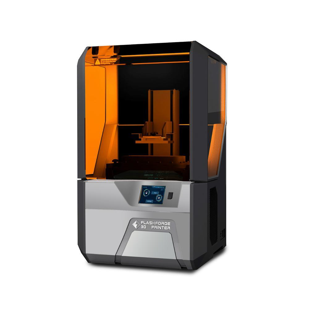
Entry-level models
Entry-level devices are available for example from Anicubic. Typically, the build space is limited (115 x 65 x 155 mm) with a minimum layer thickness of 25 ~ 100 um. Prices for usable beginner products start at 250 € without accessories. It is recommended to purchase a wash station and a curing unit. In the hobby area, this can be replaced by a simple basin with isopropanol and a UV lamp.
Prototype and development
In prototyping and development, (semi)professional DLP printers are a good way to achieve results quickly and comparatively cheaply. These devices require less maintenance than in the hobby sector. Typically, the devices cost between 2,000 € and 10,000 € (as of 2021). Typically, the build space is small (up to 200 x 200x 200 mm) but with high XY pixel resolution (60 um) and low Layer Resolution (12 um). This makes them Ideal for high detailed models. Typical manufacturers in this range are Flashforge and carima.
Materials and their properties
The following figure shows an overview of the materials that can be used for DLP. The difference between the materials that can be used in this process should become clear.
2.2.4 (MJF) 3D printing systems | Multi Jet Fusion for prototypes, components and small series.
Multi Jet Fusion (MJF), introduced to the market by HP in 2016, is a fairly new technology moving toward industrial-scale ability. As with many 3D printing technologies, MJF is a powder-based 3D printing process. It is able to create functional prototypes as well as end-use production parts relatively fast. This technology is created for a professional environment and is not intended for the hobby sector – according to the current status. Correspondingly the machines are highly developed and designed for the highest demands.
This powder bed fusion 3D printing technology is often confused with two other types of 3D printing processes: SLS and Binder Jetting. None of the three processes are identical but similar in the sense that they all use thermoplastic powder, usually nylon. While Binder Jetting uses one binding agent to glue the powder particles together and SLS uses a laser to sinter the powder selectively, the MJF process works with a couple of different agents that interact with the powder in combination with an energy source to create parts.
Accordingly, MJF gets its name from the multiple inject heads that selectively apply fusing and detailing agents across a powder bed, which are then fused by heating elements into a solid layer. These agents aren’t binders, rather they respond to the IR energy/ UV-light which is applied to it. After each layer, powder is distributed on top of the bed and the process repeats until the parts are complete. The fine-grained material, used within this process, allows very thin layers of 80 microns. This leads to parts with high density and low porosity. Because of that in combination with how the material is fused, the final parts exhibit quality surface finishes, fine feature resolution and isotropy (consistent) mechanical properties when compared to the other processes mentioned above. Isotropy properties means that there is no major difference between the x-, y-, and z-orientation, which make it superior to other (powder-based) technologies, especially with regard to the strength in the z-axis.
Industries Using Multi Jet Fusion.
MJF has found use in several industries across the board because of its versatile application. This technology can be used for development processes, from prototyping to parts production. Typical industries, among others, are Automotive, Medical Engineering and Consumer Goods.
Pre-Processing
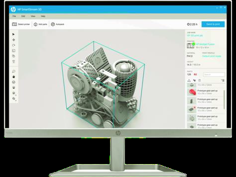
Before the actual print starts, the software, associated with the printer, takes over evaluating each part for selecting the optimal print orientation. They are then placed in the build envelope while the software takes care of a balanced height and pack density. In regards to this, the 3D file to be printed is rendered as voxels. Voxels contains the volumetric information to create the product. They represent essentially a three-dimensional equivalent of pixels that 2D printing relies on. Just like the principle of 2D printing, voxels are either fused into the final print or they aren’t.
General Process
After inserting the build unit into the processing station, the MJF printing process itself (seen in the picture above) starts by spreading a thin layer of powder across the build platform, where it is heated to a near-sintering temperature. The powder coating, applied by a recoater from top-to-bottom, has a thickness of 80 microns. Next, a carriage including the inkjet nozzles runs from left-to-right across the powder, jetting the agents onto it. A high-powered energy source passes over the building area in the same step. The process continues, layer-by-layer while the carriages change direction, until a complete part is formed.
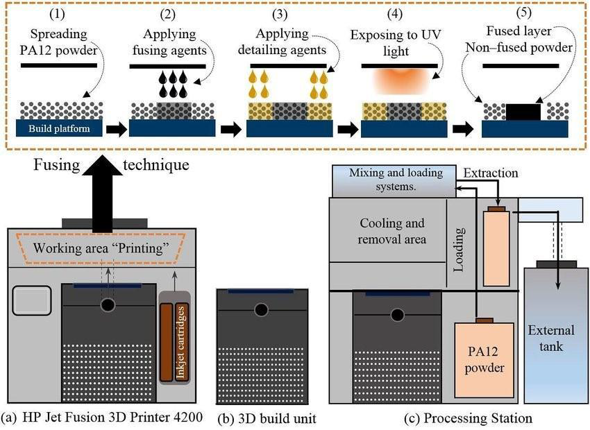
In terms of the fusion technique itself, there are effectively two agents that are printed onto the powder to increase the thermal selectivity during the printing process. The fusion agent is applied to the areas where the energy absorption should be increased. (2). The detailing agent is added to the boundaries of the part to prevent heat conduction from the part to the surrounding material. (3). That agent ensures a sharp and accurate part by effectively cooling down that area and stops the energies from being absorbed beyond the component boundaries. The fusion agent on the other hand absorbs IR energy and causes the sintering of the part areas.
Post-Processing
After finishing the process, the 3D build unit (b) including the entire powder bed with the completed parts is moved to a processing station (c). There, the cooling process begins in a controlled manner to avoid deformation. A full build naturally cools in about 24 hrs. Following this, the parts are extracted while the loose powder can be removed by an integrated vacuum. The final step is bead blasting the parts to remaining unfused powder. Depending on the usage, an optional dyeing step can be applied to achieve a uniform black finish.
Advantages and Disadvantages
Pros:
● Fast printing speed and production cycle
● Low cost per part
● Accurate printing, smooth surface areas
● Isotropy (consistent) mechanical properties
● Design freedom – no support needed
● High amount of recycled material (up to 80%) – less waste
● Ability to produce coloured parts
Cons:
●Expensive printer investment
● Limited material options
● Unable to produce hollow parts
Machine Costs
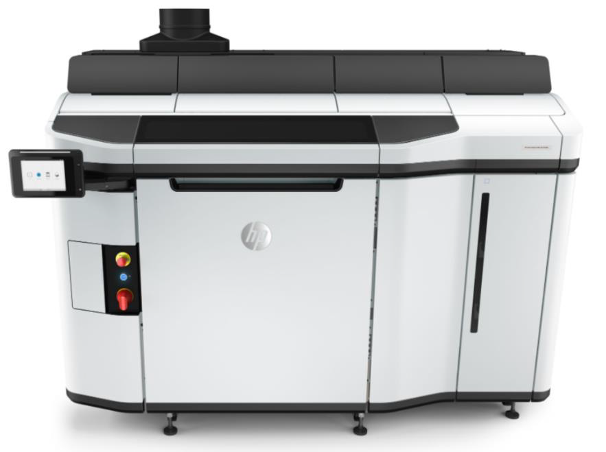
HP released various printer configurations that come with different hardware price tags, operation costs and yearly maintenance costs. The cost range of hardware across these machines is $57,000 – $500,000. However, the less expensive machines typically have a higher cost of operation. In contrast, the more expensive machines have significantly lower operating costs at a higher number of pieces. The unit cost for 100 parts is about $13.99.
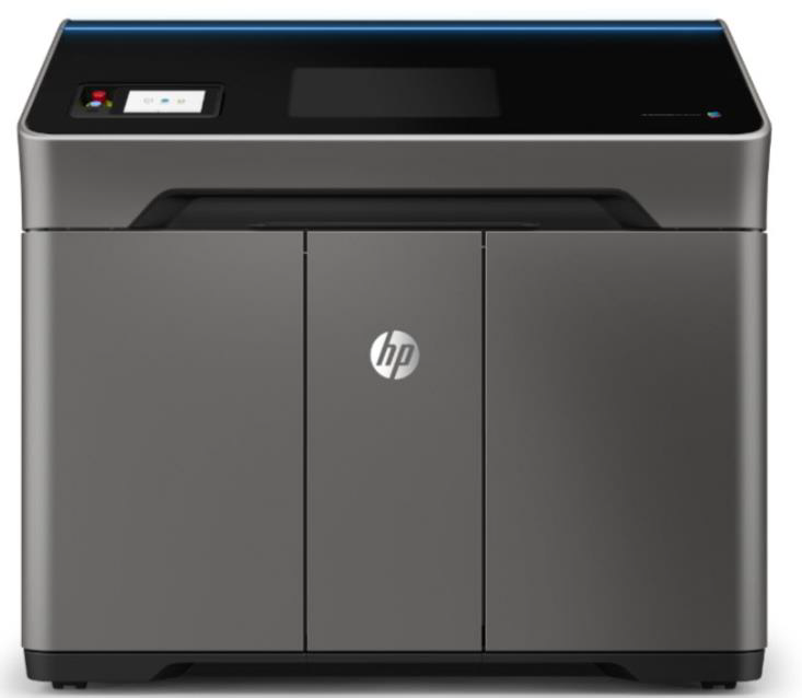
The printer shown above is one of HP’s more affordable machines, with a build volume of 254 x 190 x 248 mm. The cost of this AM machine is more than $57,000. For a printed part, which has a volume of about 15 cubic centimetres, the running costs are between $4 and $8, depending on the build height and packing density. Less than 100 parts per week can be produced. The yearly maintenance ranges from $10,000 – $15,000 per year. This includes remote problem diagnosis and support, onsite hardware support with all parts and labor included, and all firmware updates.
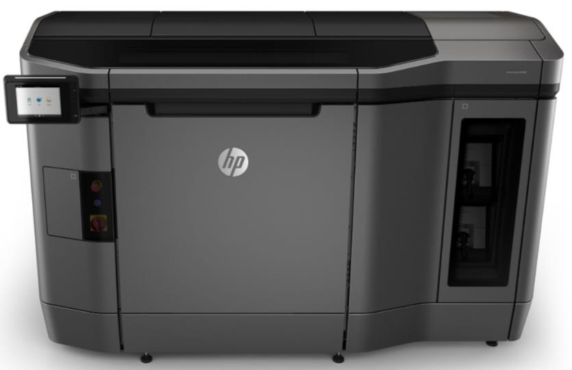
The price range for this series is $270,000 – $430,000. Because this series contains higher end machines than the 300/500 series, the printing costs are less expensive. They can achieve $2 – $4 per 15 cubic centimetres of printed part. The printer from this series can produce between 300 and 1000 parts per week and enables the entry into digital small batch parts production. With regard to the annual maintenance costs, which depend on the exact hardware configuration, such as the number of build units, printers and processing stations, these are generally higher at $35,000 to $43,000 per year.
The HP 5200 machines are the latest evolution of HP’s Multi Jet Fusion technology. These machines are designed for actual manufacturing operations. The hardware costs are in range of $350,000 to $500,000, but the reliability, accuracy and low cost per part are unmatched in the industry. These machines can achieve a price of less than $1 per 15 cubic centimetres of printed part. With a build volume of 380 x 284 x 380 mm 300 to 1500 parts con be produced per week. The annual maintenance for this high-end production printers is $35,000 – $53,000.
Materials and their properties
The following figure shows an overview of the materials that can be used for Binder Jetting. The difference between the materials that can be used in this process should become clear.

2.2.5 (EBM) 3D Printing Systems | Electron Beam Melting
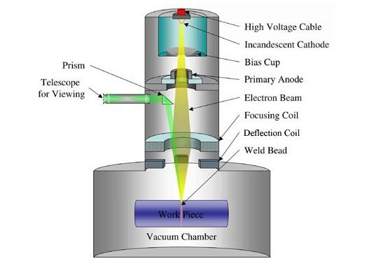
The following figure shows the general structure of an EBM printer. The parts functions and the general process will be explained in the following.
Electron Beam Melting (EBM), first introduced to the market in 2002 by the Swedish company Arcam, is an additive manufacturing process for the production of metallic components from a powder bed and is therefore part of the “Powder Bed Fusion” family. As you have already learned, plastics are often used for industrial 3D printing. However, 3D metal printing in particular offers a wide range of advantages and is accordingly gaining more and more acceptance in the industry.
Like its name implies, this technology uses an electron beam as a heat source to fuse metal particles, primarily titanium alloys, and create the desired part layer by layer. The EBM process is performed in a vacuum, making it a suitable AM process for the production of materials that have a high affinity for oxygen. This technology is not able to print plastic or ceramic parts. This is because the technology is based on electrical charges. These charges create the reaction between the powder layer and the electron beam, causing the former to solidify. This process enables the production of complex, highly durable and at the same time lightweight structures. The technology is mainly used within the aerospace and medical industries and was developed for industrial application only. EBM produces parts faster than laser melting, but usually the result is less accurate and the surface is of lower quality because the powder is coarser-grained. It is worth mentioning that the company was acquired by GE Additive in 2016 and is now the only company marketing machines based on this process.
Pre-Processing
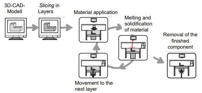
Before the actual printing process can begin, the 3D model is sent to a slicer software, which cuts the object into several layers corresponding to the material layers. The slicer, which was specially developed for the printer, sends all this information directly to the printer, which can begin its manufacturing process. The metal powder can then be filled into the machine’s tank and the internal pressure has to be set to around 0.0001 mBar.
General Process
The printing process itself starts with spreading a thin layer of powder onto the build surface coating this area. Each layer is preheated with a defocused beam (700-1000 °C), and then the shape of the part is selectively melted, similar to SLM. The system repeats the process for each cross-section of the 3D CAD model until the shape of the required part is achieved.
Note that the entire manufacturing process must be done under vacuum to operate the electron beam properly. This also prevents the powder from oxidising when heated. At the end of the production process much of the unmelted powder can be almost directly reused.
For overhanging structures support structures are needed to help direct heat away from the molten powder to prevent wrapping and swelling of the part. However, residual stresses are low due to the preheating step for each powder layer, which helps keep heat in the build. In addition, both the energy density and scanning speed of the electron beam are generally much higher than SLM, making the build speed faster.
Post-Processing
After the manufacturing process is complete, the parts have to be removed from the machine. This starts by removing the excess powder with a blow gun for example. In the further process, the supports are removed, if any, and the components are detached from the plate. Further steps may include possible machining of the surfaces, polishing and coating using traditional techniques. In some cases, it may be necessary to heat the part in an oven for several hours to relieve the stresses slowly caused by the manufacturing process.
Advantages and Disadvantages
Pros:
● Production speed: The electron beam can separate to heat the powder in several places at once
● High density parts (up to 100%)
● High mechanical resistance of the printed parts
● Weight reduction
● Low risk of deformation
● Most of the unused powder can be recycled
Cons:
● Long cooling process
● Expensive to purchase and use
● Limited range of metals
Materials and their properties
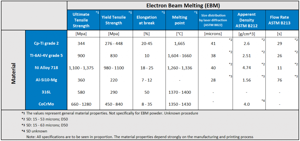
Only a limited number of metals can be used within the EBM process, including titanium alloys, cobalt chrome, steel powder and nickel alloy 718. These materials have high strength, corrosion resistance and very good mechanical properties. For this reason, they can also be used for demanding applications in terms of load. It is important to note that any material used for EBM must be conductive, as the process relies on electrical charges. Currently, EBM is the only commercial AM solution for additive manufacturing of titanium aluminide (TiAl) parts. This material is particularly known for its light weight, strength and heat resistance. The following figure shows an overview of the materials that can be used for EBM. The difference between the materials that can be used in this process should become clear.
2.2.6 (SLS) 3D Printing Systems | Selective Laser Sintering for Series Parts.
The SLS Selective Laser Sintering in plastic and metal for end products and small series.
General process
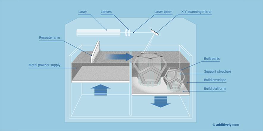
In selective laser sintering (SLS), a layering apparatus called a recoater distributes layers of powdered material, which are then fused together by a laser. This process allows a wide variety of materials to be processed, including plastics, metals and ceramics.
Other mechanisms involved in the process include a protective gas system and sometimes a powder preheating system. SLS can be used for polymers, metals and ceramics. SLS machines use a variety of lasers, including CO2, Nd:YAG, disk lasers and fiber lasers. This technology can create parts that are finely detailed, strong, durable, heat resistant and flexible (if needed).
Choosing the right laser is important because it significantly affects the way the powder fuses. The ability of the laser to absorb into the material depends on the laser wavelength used, while the densification of the powder depends on the correct laser energy density.
Selective Laser Sintering is mainly used in the professional environment. There is hardly any use in the hobby sector. Accordingly, the machines are highly developed and designed for the highest requirements. Traditional industrial SLS 3D printing systems use single or multiple high-powered lasers. The printing process requires an inert environment – nitrogen or other gases – to prevent oxidation and decomposition of the powder, which necessitates special air treatment equipment. These machines also require a dedicated HVAC system and industrial power, and even the smallest industrial machines take up at least 10 square metres of installation space.
Meanwhile, there are printers for the semi-professional area from about 10000€. Printer manufacturers of professional equipment often boast that SLS prints compete with injection molded products in terms of strength and precision.
Typical industries are the following:
● Automotive.
● Templates and fixtures.
● Sand casting models.
● Tooling.
● Aerospace.
● Medical and healthcare applications.
● Consumer electronics.
● Packaging.
● Military applications.
SLS printers have a more limited plastic material range than technologies like FDM, mostly limited to nylon polyamide powder. Some are limited to black PA12 only, while others can print powders such as PA11 and PA6. In the industrial area, glass blends, carbon fiber blends and even food-grade powders are also being used for niche applications. More and more SLS printers can print TPU, a flexible rubber-like material. Metal powders can also be sintered, but these are more commonly produced using the art-managing DMLS process.
Process flow – printing, cooling, finishing
Printing: the powder is spread in a thin layer on a platform in the build chamber. The material is preheated to just before the melting point. The laser then scans a cross-section of the 3D model and heats the powder to just below or directly to the melting point of the material. This mechanically fuses (sinters ) the particles together, creating a solid part. The unfused powder supports the part during printing, eliminating the need for special support structures. The platform then lowers one layer into the build chamber, typically between 50 and 200 microns, and the process repeats for each layer until the parts are complete.
Cooling: after printing, the build chamber cools in a controlled manner. This is done to avoid warping and to achieve the best possible material properties. This process can take longer than the actual printing process.
Finishing: the finished parts must be removed from the build chamber, separated and cleaned of excess powder. The powder can be recycled and the printed parts can be further processed by blasting or tumbling.
Advantages and Disadvantages
Each manufacturing process has its individual advantages and disadvantages. The following are the main advantages and disadvantages of SLS.
Pros:
● SLS parts are stable and suitable for highly functional parts
● Complex geometries possible
● Integration of different part functions
● Prototypes & end user parts
● No support required / Self-supporting
● Low residual stresses
● Process stability
● Good mechanical properties
● Low anisotropy
● No tooling required
Cons:
● Rough surface of the parts
● Surface porosity of the parts (Solution: application of sealant)
● High cleaning effort after printing
● Protective equipment needed for very fine powders
Materials and their Properties
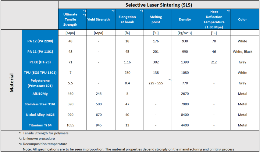
Typical materials used in SLS are PA12, PA11, PEEK, PEBA (TPA), Alumide, Carbon filled polyamide and Glass filled polyamide. An overview of the properties can be found in the following table.
2.2.7 (SLM) Selective Laser Melting Systems
Selective laser melting (SLM) started in 1995 at the Fraunhofer Institute ILT in Aachen, Germany, with a German research project. It is an industrial metal 3D printing process that builds objects layer by layer using high-power laser beams to fuse and melt metallic powder together. A range of metals produce final parts that can be used for end-use applications. These parts fulfil high material requirements, such as very good thermal resistance and mechanical resilience. Accordingly, SLM is considered one of the most versatile 3D printing processes and is a real alternative to welding, milling or casting material.
The innovation potential of laser melting is very high, because manufacturing no longer limits design possibilities. Components that were very expensive or impossible to produce are suddenly realisable, even for very small quantities. On the one hand, selective laser melting is often used in rapid prototyping. But on the other hand, the 3D printing process is also a valid option to conventional processes for the production of small series. In addition, this process is being used more and more for components that are based on a very complex or lightweight design.
Therefore, it is not only the classic customers of high-tech components such as aerospace or the automotive industry who benefit from this. Sectors such as mechanical engineering, toolmaking or medical technology also enjoy the benefits of 3D metal printing today.
General Process
To get started, loose powder is applied in a thin layer evenly on the building platform with the help of a blade or a roller. One or several laser beams are then deflected onto the powder surface so that the focus point of the laser traces the contours of the component layers. The cross-section area of the designed 3D part is then built by selectively melting and re-solidifying the metallic powders. To create another layer, the build platform is lowered by the layer thickness and a new layer of powders are deposited and levelled by the recoater again. To complete the building process, the steps are repeated until all layers have been fused and melted together according to the CAD Design.
Advantages and Disadvantages
Pros:
● Dense functional parts made of various metallic materials.
● highly complex geometries and moving parts can be realised.
● Tool-free production, extremely fast and reliable.
● High mechanical resistance.
● Good reworking possibilities.
● Low waste.
Cons:
● Expensive.
● Special skills and knowledge in design and manufacturing are required.
● Relatively large machines.
● limited to relatively small parts.
● rough surface finish – post-processing needed.
Materials and their Properties
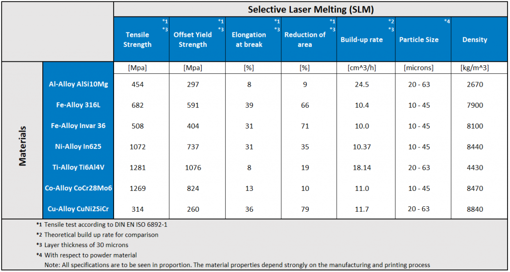
The following figure shows an overview of the materials that can be used for SLM. The difference between the materials that can be used in this process should become clear.
2.2.8 (DED) Directed Energy Deposition Systems
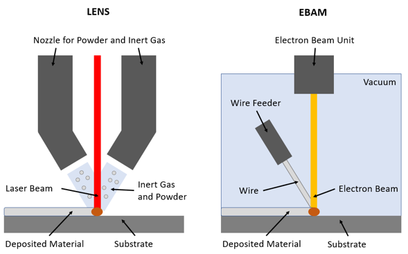
There are several Directed Energy Deposition (DED) processes in existence. Among the most relevant are Laser Engineering Net Shape (LENS) and Electron Beam Additive Manufacturing (EBAM). The following figure shows these two processes and their structure. The core element of LENS is the nozzle, which delivers a combination of inert gas and powder towards the base plate. The powder is then melted by a laser. EBAM, on the other hand, uses wire that is provided by a wire feeder. This wire is melted by using an electron beam. Therefore, the process must take place in a vacuum, otherwise the electron beam would interact with electrons from the atmosphere.
General Process
The Directed Energy Deposition (DED) uses an energy beam to directly melt material onto a substrate. This energy beam can be a laser or an electron beam. The energy beam used depends on the exact process that is chosen. The processes are generally based on a nozzle or a feeder with a beam unit that is mounted to a multi axis arm and a base plate which, depending on the machine, can be static or also multiaxial.
In general, DED often uses metal wire or powder to process. The variety of possible metals is high: titanium, Inconel, tungsten, stainless steel, steel, aluminium, copper and nickel as well as many other metals. The metal wires can vary between 1-3 mm and the diameter of the powder between 50-150 microns. Also, polymers and ceramics are possible to manufacture but play a rather subordinate role. Due to its fixed cost structure, post-processing requirements and low resolution DED is used in low volume manufacture of middle or big sized parts. Some industry sectors where these boundary conditions for near-net-shape parts are present are aerospace, defence, energy and marine. Feature addition and repair bring revolution to a market. Previously, these tasks could only be done manually.
With DED already existing parts can be modified or repaired automatically with a good accuracy.
Advantages and Disadvantages
The following list shows the main advantages and disadvantages of DED in general, without differentiating into further subcategories such as LENS or EBAM. The other manufacturing methods serve as a reference for comparison. If a point refers to something specific, this is indicated in brackets.
Pros:
● High build rates
● Dense and strong parts
● Material and manufacturing costs are low
● Near net shape (cf. machining)
● Wide range of metal materials
● Large build size
● Editing and repairing existing parts
Cons:
● Low print resolution
● Low volume manufacturing
● Gas / vacuum chamber or local shielding needed
● High energy consumption
● High capital cost
Materials and their properties
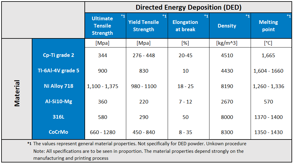
The following figure shows an overview of materials that can be used for DED. Material for DED can be in wire or powder form. Therefore, only the general mechanical and physical properties are given in the following table.
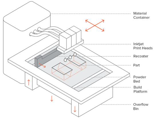
2.2.9(BJ) Binder Jetting Systems
The following figure shows the general parts of a Binder Jetting (BJ) printer. The parts’ functions and the general process will be explained in the following.
General Process
In general, Binder Jetting uses a binding agent which is applied on powder to glue it together. This powder can be made out of metals or ceramics (sand). Furthermore, it is possible to not only provide binding agent through the nozzle but also multi-colour ink to create colourful parts. Colours are generally used with ceramics to create prototypes, visual models, or decorative items. It is also possible to create sand casting cores and molds with BJ, as well as metal parts. When using metal powder to create final parts it is important to note that BJ only creates green parts. These must then be post-processed to reach good mechanical properties. Processes to increase the mechanical properties are infiltration and sintering.
As all additive manufacturing processes, BJ is also a layer-by-layer process. Therefore, the recoater is used to provide the build platform with a thin layer of the chosen powder. The powder is provided by a powder bin and the excess powder is stored in an overflow bin. In the next step the inkjet print head travels over the powder bed and supplies specific areas with binding agent and optionally also with coloured ink. The areas where the binding agent must be applied in every layer is defined by the pre-processing software. After finishing a layer, the build platform will be lowered by one layer and the recoater again provides the build platform with new powder. This process will be repeated until the part is fully built. Depending on the chosen material, post-processing is needed after removing the parts from the building plate and the excess powder from the part with pressurized air.
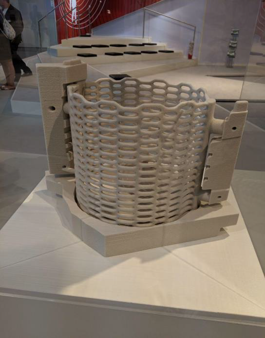
One of three big application areas are sand casting models. Models created by BJ can have an intricate shape because of the powder that surrounds the printed part. This allows the creation of casting models that are not possible with conventional processes. As a binding agent, furan binder is commonly used. Also, large casting models can be created at relatively low cost. Furthermore, there is no need for post-processing. The printed cores and molds can directly be used for casting.
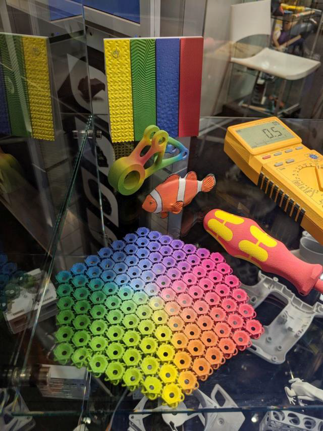
Also, it is possible to print multicolour models with BJ. These multicolour models can function as prototypes, visual models (e.g., in architecture) or decorative items and are widespread because of the low costs. The models are generally made from sandstone or PMMA powder. Phenol and silicate binder are commonly used as a binding agent in this area of application. After the printing process is finished, cyanoacrylate is often used to improve the mechanical and visual properties of the part.
The third area of application is models out of metal. Metal powders which can be used for BJ are stainless steel, inconel, copper, titanium and tungsten carbide. A liquid polymer binder is generally used in the process as a binding agent. Metal Binder Jetting can be used in low-to-medium production and enables one to create intricate shapes without the need of support material. During the BJ process green parts are being created. Therefore, post-processing is needed in the form of infiltration or sintering. The post-processing must be taken into account in the modelling process, because it has an impact on the geometry due to shrinking.
Advantages and Disadvantages
The following list shows the main advantages and disadvantages of Binder Jetting, without differentiating into further subcategories such printing ceramics, metals and composites. The other manufacturing methods serve as a reference for comparison. If a point refers to something specific, this is indicated in brackets.
Pros:
● Multifunctional (Prototypes, final metal parts, sand casting cores and molds)
● High resolution (up to 30 microns)
● Low cost printed parts
● No distortion or curling during the process
● Full color options
● Large build volumes
● Multiple parts at once printable
● No support structures needed
Cons:
● Metal parts need to be sintered or infiltrated
● Metal parts have lower mechanical properties than DMLS/ SLM parts
● Limited material selection
● Shrinking during infiltration and sintering
● Low mechanical properties in green state
Materials and their properties
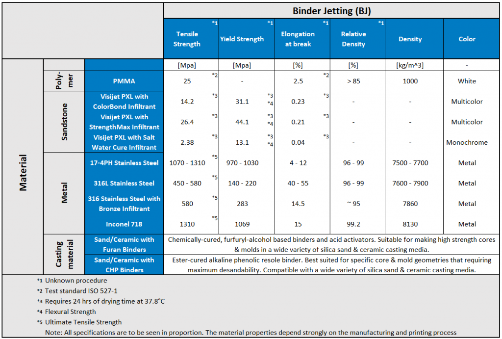
The following figure shows an overview of the materials that can be used for Binder Jetting. The difference between the materials that can be used in this process should become clear.
2.2.10 (PolyJet)Material Jetting
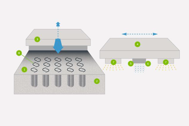
The following figure shows the general parts of a Material Jetting (MJ) printer. More precisely, a polyjet printer is shown. It is often the case that Material Jetting and Polyjet are equated, as this is the first patented process in this field
General process
Material Jetting is divided in three main subcategories. These subcategories are: Drop on Demand, NanoParticle Jetting and Polyjet. Polyjet was the first and is still the most important process in Material Jetting. Therefore, this unit will give a quick overview about all three subcategories and will then focus on Polyjet.
Drop-on-Demand (DOD)
DOD printer use two print heads. One that provides the build platform with the liquid build material and the second one that provides the platform with support material. These printheads only deposit dots on the build platform where it is needed. That is the name giving property of DOD. Additionally, DOD printers flatten each printed layer after the material is deposited, so that the next layer has a flat surface to build on. Because of the use of viscous liquid, wax is commonly used in this process. This process is often used in the manufacture of jewellery or generally to produce molds.
Process: Nano Particle Jetting (NPJ)
NPJ uses, as the name implies, nano particles that are surrounded by a liquid. This is called dispersion. The dispersion is then jetted on the build platform to create very thin layer of build material as well as support material. The build platform is constantly in a high temperature environment so that the liquid in which the nano particles are dispensed evaporates and only a dense layer of nano particles is left on the build platform. After the building process is finished the parts must be sintered to reach the desired properties and the support structures must be removed. The process is used to create parts out of ceramics or metals in a technical environment. The metal parts are very dense, and they can have the same properties as the parts from ordinary manufacturing processes after sintering.
Process: Polyjetting
Polyjetting or generally also called Material Jetting (MJ) is a multi-purpose and fast printing technology. The technology uses photopolymer resin droplets and a UV light source to build complex parts in the typical layer-by-layer process. Generally, the layer thickness is very thin. Because of this and because the material used is present in the liquid phase, the resolution of this process is very high and the surface very smooth.
The process of Polyjetting begins with preheating the resin, so that the viscosity is sufficient to further process it. Then the print head navigates above the build platform and a nozzle deposits the liquid resin droplets of the photopolymer. After depositing the liquid resin droplets, UV light cures the resin on the build platform through photopolymerization. The resin is now solidified. After this process is done for the whole layer, the platform is lowered by the layer height and the process starts again. The difference of this process compared to many others lies in the deposition of the material. Polyjetting uses multiple inkjets to deposit multiple materials at the same time. Therefore, it is possible to create multicolour parts and parts out of different materials as well. The support structures that are produced in the printing process must be removed in post-processing.
Advantages and Disadvantages
The following list shows the main advantages and disadvantages of Material Jetting, without differentiating into further subcategories such as DOD, NPJ and Polyjet. The other manufacturing methods serve as a reference for comparison. If a point refers to something specific, this is indicated in brackets.
Pros:
● Multi-color
● Multi-material
● Very smooth surface finish
● Very good resolution
● Homogeneous mechanical and thermal properties
● High production rate (multiple parts at once)
Cons:
● Low mechanical properties (Except NPJ parts)
● UV sensitive
● Support structures needed
● Brittle parts
● High costs
● Properties degrade over time
Materials and their properties
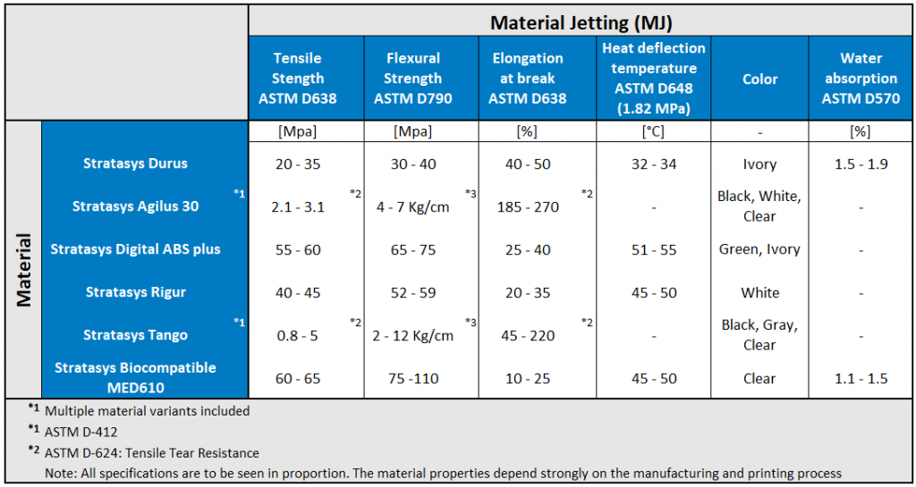
The following figure shows an overview of the materials that can be used for Material Jetting. The difference between the materials that can be used in this process should become clear.